
Quick answer: Size the wall from the operator seats, with the bottom edge commonly about 48 to 52 inches above the floor. Count the sources and window layouts you need at the same time, then choose the architecture: a video wall processor for a small fixed wall, AV over IP for large or growing walls, and extenders or fiber to bring distant sources to the wall.
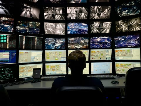
A control room video wall usually gets specified after the room itself: the shell is built, the console furniture is ordered, and then someone has to decide how big the wall needs to be, how many pictures it needs to show at once, and what actually pushes those pictures onto it. Product literature covers displays, mounts and mullion width in detail and says almost nothing about that decision chain. This guide works through it in order: sizing the wall from the seats in the room, inventorying the sources and layouts it has to carry, choosing between a processor, an AV over IP system and a matrix switcher to drive it, and getting distant sources to the wall once the architecture is set.
Sizing a control room video wall
Start from the seats, not the wall. A control room video wall is only useful if every operator position can read it, so the wall's height, width and mounting position all follow from where people actually sit and how far back the farthest seat is. A wall sized for a demo on an open floor can be unreadable once the same room is fitted with consoles, overhead lighting and a row of seats well back from the wall.
Mounting height matters as much as overall size. A widely used guideline places the bottom edge of a control room video wall about 48 to 52 inches above the floor, high enough to clear operator console monitors without pushing the top of the wall out of a comfortable sightline (Diversified). Treat that range as a starting point, then check it against the actual seats and console height in your room, since a taller console or a raised platform changes where the bottom edge needs to sit.
For an LED video wall, pixel pitch and viewing distance are the two numbers that decide legibility. A finer pixel pitch supports viewers sitting closer to the wall without individual pixels becoming visible, while a coarser pitch is fine when every seat is farther back. Run your own pitch and distance numbers through the LED video wall calculator before settling on a wall size, since the right pitch for a dispatch room with seats close to the wall is not the same as the right pitch for an operations floor with seats far across the room.
An LCD video wall trades pixel pitch for bezel width. Even a narrow-bezel display leaves a visible seam between panels, and that seam interrupts anything that spans multiple displays: a wide camera feed, a map, or a single application stretched across the wall. Content that stays inside one panel does not run into this problem, which is part of why window layout, not just overall wall size, is a real design decision rather than an afterthought.
Sources and window layouts
Before choosing hardware, inventory what the wall actually has to show. A typical control room feeds its wall from security or process cameras, operational dashboards, mapping or GIS applications, a news or weather feed, and whatever software applications operators run day to day. Some of those sources need the whole wall to themselves at times; others only ever need a small window.
The two layout patterns worth planning for are a single source spread across the entire wall and several sources shown at once in separate windows. A large map or a single camera feed benefits from filling the wall, while a shift that is watching several camera groups, a dashboard and a status feed at the same time needs the wall split into windows instead.
A dedicated video wall processor such as the KD-VW4x4ProK handles the first pattern directly, spreading a small number of inputs across a fixed wall in 2x2, 4x1, 3x1, two 2x1, or 1x4 layouts, so the operator picks the layout that matches the sources on hand instead of being locked into one grid.
The second pattern, several sources in windows at once on a single display, is what a multi-view processor is for. The KD-MLV4x4Pro offers 5 default layouts plus custom presets on a display, so a shift can switch between a quad view, a full-screen view and a custom arrangement without moving cables or swapping hardware.
Choosing a processor, AV over IP or a matrix
Once the sources and layouts are known, the video wall architecture follows from two things: how big the wall is today, and how much it is likely to grow. A small, fixed wall with a known input count works well with a processor. A wall that already spans many displays, or one a facility expects to expand, is better served by an AV over IP system that can add sources and displays without replacing the core hardware. A facility that just needs to route any of several sources to any display, without combining or windowing them, has a matrix switcher problem rather than a video wall problem.
| Need | Approach | Key Digital option |
|---|---|---|
| Small fixed wall, up to four displays | Video wall processor | KD-VW4x4ProK |
| Several sources in windows on one display | Multi-view processor | KD-MLV4x4Pro |
| Large or growing wall, many sources | AV over IP | KD-IP1022ENC-II encoders and KD-IP1022DEC-II decoders, walls up to 16x16 (256 displays), under 40 ms latency at 4K |
| Route any source to any display without wall processing | Matrix switcher | KD-MS8x8G-2 |
The video wall and multi-view processors category covers the KD-VW4x4ProK and KD-MLV4x4Pro directly. For a wall built on AV over IP encoders and decoders, every display gets its own decoder and every source its own encoder, all riding the same network switch, which is what lets the wall in the table above scale to 16x16, or 256 displays, without adding a dedicated wall processor at all. For pure any-source, any-display routing without windowing, a matrix switcher such as the KD-MS8x8G-2 stays simpler than either a wall processor or an AV over IP deployment sized for far more displays.
Video wall parts
| Part | Role in the system | Note |
|---|---|---|
| KD-VW4x4ProK | Video wall processor | 2x2, 4x1, 3x1, two 2x1 or 1x4 modes |
| KD-MLV4x4Pro | Multi-view processor | 5 default layouts plus custom presets |
| KD-IP1022ENC-II | AV over IP encoder at each source | Walls up to 16x16 with matching decoders |
| KD-IP1022DEC-II | AV over IP decoder at each display | Under 40 ms latency at 4K |
| KD-MS8x8G-2 | Matrix switcher, 8 sources to 8 displays | Any source to any display |
| KD-X444LP | Brings a distant source to the wall over CAT | 4K to 70 m on CAT5e/6, 100 m on CAT6A STP |
Getting sources to the wall over distance
A video wall rarely sits next to every source that feeds it. Cameras, workstations and servers are commonly in a separate equipment room or spread across a facility, so the signal path from source to wall has to cover real distance without degrading the picture.
For a source close enough for a single point-to-point extender, the KD-X444SP carries a 4K signal up to 50 m over one CAT cable, and the KD-X444LP reaches farther, up to 70 m on CAT5e/6 or up to 100 m on CAT6A STP, still at 4K.
Where the run is long and a single CAT cable will not reach, an active optical HDMI cable such as the KD-AOCH328P connects like an ordinary HDMI cable, with no separate transmitter or receiver box, and carries a 4K signal up to 100 m on one run.
An AV over IP deployment covers distance a different way. Each encoder or decoder in an AV over IP encoders and decoders system connects to the network switch over its own cable run, and that run can be up to 100 m, so a source or a display anywhere within that reach of a switch joins the same video wall system without a dedicated point-to-point cable running to every other endpoint.
A console operator's own workstation can also reach the wall without adding new source hardware. A presentation switcher at the console mirrors its HDMI and HDBaseT outputs, so the same picture the operator sees on a desk monitor also goes out to the wall at the same time, with no splitter added to the signal path. See the 911 dispatch console AV guide for how a console position wires into a shared wall.
EDID and HDCP with mixed sources
A wall fed by several different kinds of sources, cameras, PCs and media players, is really a wall fed by several different kinds of sources talking to it through EDID, the handshake that tells a source what resolution and format the display accepts. When every source in the room negotiates its own format independently, one PC can end up outputting a resolution the wall does not handle cleanly while another outputs something else entirely.
Setting a single, consistent EDID for the whole system, rather than letting each source negotiate on its own, keeps every source outputting a format the wall is built to accept. That one decision heads off a large share of the black-screen and wrong-resolution problems that show up once a wall goes live with sources it was never tested against.
Any source carrying HDCP-protected content needs HDCP support at every stage between that source and the wall, not just at the two ends. A single unsupported link anywhere in the chain, an extender, a switcher, a splitter, blocks the picture at that point, even if the source and the final display both support the protection on their own.
Test every source on the actual wall, in its actual layout, before handover. A source that looked fine on a bench monitor can still surface a resolution mismatch, an HDCP failure, or a color issue only once it is running through the full signal path to the wall.
Small walls and large walls
A small control room, a two-operator dispatch desk or a compact monitoring station, usually needs nothing more than a 2x2 or 3x1 video wall driven by a single processor. The KD-VW4x4ProK covers that footprint directly, with a fixed, known input count and no network configuration to manage.
A larger or expanding operations floor is a different problem. A wall that already spans many displays, or one that is likely to grow as the facility adds cameras, dashboards or seats, is a better fit for AV over IP, since adding a source or a display is a matter of adding another encoder or decoder to the network rather than replacing a fixed processor.
Whichever architecture fits today, plan spare capacity into it. A processor with every input already committed has no room for one more source, and an AV over IP system sized exactly to today's display count leaves no headroom for the next expansion. A little slack in either direction costs less during the original design than it does once the wall is live and a new source needs to go somewhere.
Frequently asked questions
How do you design a control room video wall?
Start from the operator positions: size the wall so it is readable from every seat and place the bottom edge above the console monitors. Then count the sources and layouts you need at once, and choose a processor, AV over IP or a matrix to feed it.
What drives a control room video wall?
A video wall processor or an AV over IP system. A processor takes a fixed number of inputs and spreads them across a small wall. AV over IP encoders and decoders scale to large walls and many sources.
How large a video wall can Key Digital drive?
The KD-VW4x4ProK drives walls in 2x2, 4x1, 3x1, two 2x1 or 1x4 modes. Key Digital KD-IP1022 -II encoder and decoder systems build walls up to 16x16, or 256 displays.
What latency does AV over IP add to a video wall?
Key Digital KD-IP1022DEC-II decoders are specified at under 40 ms at 4K, and less at lower resolutions.
How high should a control room video wall be mounted?
A common guideline places the bottom edge about 48 to 52 inches above the floor, so operators can see the wall over their console monitors. Check the sightlines from your actual seats.
Related guides
Questions about control room video walls?
Send it to a Key Digital engineer. We reply within one business day.
Message sent
Thanks. A Key Digital engineer will reply to your email within one business day.