
Quick answer: Pick the equipment location first, then pull CAT cable to the bay for the Key Digital system you use. On a KD-PS42 system, the receiver sits at the projector and the switcher's HDMI output feeds the nearby TV. A KD-UPS52U system is wired the other way round: HDMI goes to the projector, and the KD-X100MRx receiver sits at the nearby TV, carrying the picture and USB over a single CAT cable so the TV works as a touch screen. Run a second CAT cable to each bay if you install an input plate, and terminate every run to 568-B without couplers. Then connect the PC to a KD-PS42 (runs to 40 m at 4K) or a KD-UPS52U (runs to 100 m, or USB at the bay), its receiver, and the mirrored output. Test every input and display before you close the walls.
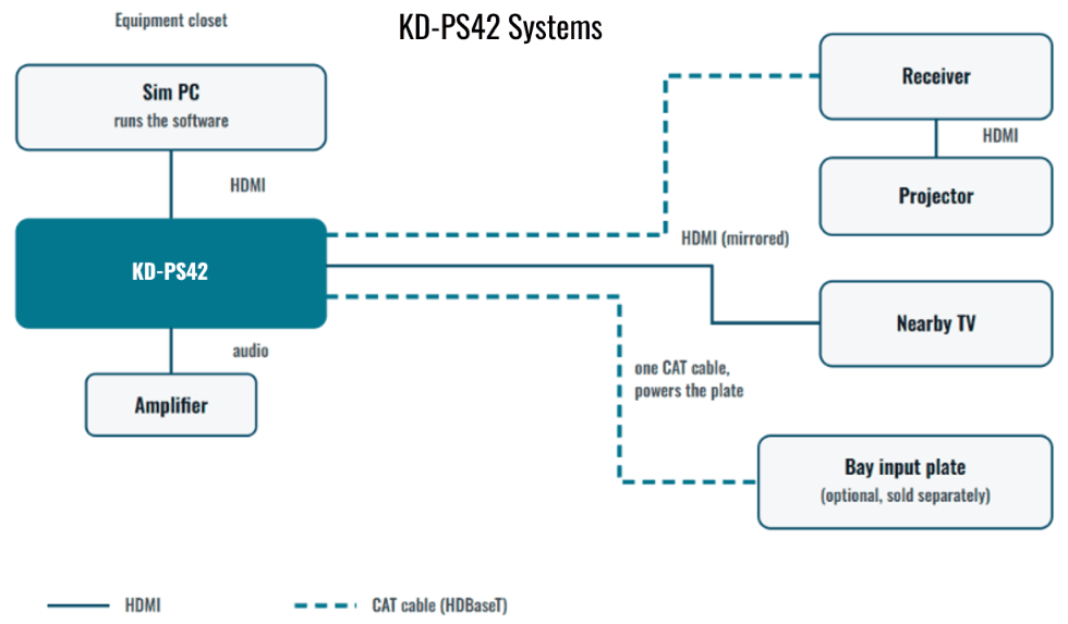
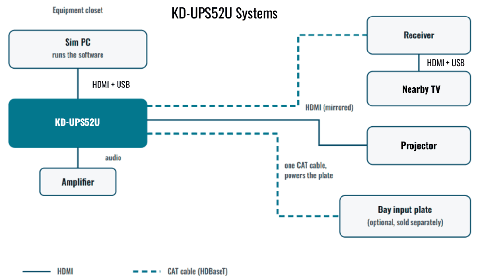
This is the wiring checklist an installer works through bay by bay: pick the equipment location, pull and terminate the cable, mount the input plate in the bay, connect the switcher and receiver, mirror the picture to a second display, wire the audio, set up USB and control, and test everything before the walls close. Work through the steps in order the first time, since a later step, like the wall plate you install, depends on the switcher you chose in the first one.
Step 1: Plan the equipment location
Pick a closet, a cabinet or a rack outside the hitting area for the sim PC and switcher before any cable is pulled. Give the location enough ventilation for the equipment to run continuously, a nearby power circuit, and enough room to service the PC later without disturbing the bay itself. A PC kept right beside the projector can sometimes run on a short passive HDMI cable, reliable to roughly 15 to 20 feet at 4K (see how long an HDMI cable can be), but moving the PC to a closet or rack almost always puts the run past that mark, which is why the rest of this guide wires the bay with CAT cable instead.
Once the location is set, measure the actual cable route from that point to the projector mount, to each TV position, and to the bay input plate if the bay will use one. Measure the real path the cable will take, including any climb up a wall or run across a ceiling, not the straight-line distance between two points on a floor plan.
The farthest of these runs decides which switcher the whole bay is built around. A Key Digital KD-PS42 covers any run up to 40 m at 4K, and a KD-UPS52U covers a run up to 100 m at 4K. If you are not sure how a given distance and resolution combination breaks down, use the cable run calculator below before buying anything.
A finished closet, a rack in a back room, or a cabinet built into the lounge millwork all work as an equipment location, as long as the sim PC and switcher can vent properly and nobody has to open a panel or move furniture to reach a control button or a cable. Settle on the location before ordering the switcher, the receiver or any wall plate, since changing it later usually means re-measuring every run in this step and possibly switching between the KD-PS42 and KD-UPS52U paths.
Step 2: Pull and terminate the CAT cable
Pull one continuous CAT5e or CAT6 cable for each HDBaseT link: one to the projector, one to each TV, and one to the bay input plate if the bay has one. A single unbroken cable for each link is what Key Digital's own installation manuals call for; they advise against joining two shorter cables with a coupler or leaving excess cable coiled at either end, both of which the manuals list as sources of trouble on an HDBaseT run.
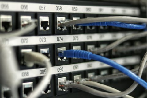
Terminate every cable to the 568-B standard on both ends. Label each end as you land it, the termination point at the closet and the destination at the other end, since a bay can easily end up with four or five CAT runs converging in the same location. Test every run with a cable tester before any wall or trim goes on, so a bad termination gets found while it is still easy to fix.
If the walls are still open at any point in the build, whether that is new construction or a chance to run cable through a basement or a garage, use that window to pull every CAT run the bay is likely to need, including a spare run to the input plate location even on a build that will not wire one in right away. Pulling one extra cable while a wall is open costs far less in time and drywall than opening it again later.
Step 3: Install the bay input plate
Install a KD-X2x1WDTx wall plate in the hitting area for the KD-PS42 path, or a KD-X4x1WUTx wall plate for the KD-UPS52U path. The KD-X2x1WDTx is a dual-gang plate with HDMI and DisplayPort inputs and works only with the KD-X40MRx receiver or the KD-PS42 switcher, while the KD-X4x1WUTx is a 3-gang plate with two HDMI inputs, DisplayPort and USB-C video, and it also extends USB 2.0, IR and RS-232 to the bay.
Both plates are sold separately from the switcher and are powered over the same CAT cable by the switcher, so there is no separate power outlet needed at the plate itself. Once the plate is wired in, auto-switching takes over: plugging a laptop or another guest source into the plate selects it automatically, without anyone touching a control.
Manual control can be selected instead of auto-switching when a fixed source assignment is preferred, which some venues choose so a specific input, such as the sim PC rather than a guest laptop, always stays live for staff at a front desk to select without guesswork.
Step 4: Connect the PC, switcher and receiver
Connect the sim PC to an input on the switcher. The KD-PS42 has three HDMI inputs plus one HDBaseT input, and the KD-UPS52U has two HDMI inputs, DisplayPort, USB-C video and one HDBaseT input. If the PC only outputs DisplayPort, choose the KD-UPS52U or route it through the bay input plate instead, since the KD-PS42 has no DisplayPort input of its own.
From the switcher, run the HDBaseT output over the CAT cable pulled in Step 2 to the receiver at the projector or the nearby TV. A KD-X40MRx is included with the KD-PS42 and goes at the bay's projector: connect the receiver's HDMI output into the projector. A KD-X100MRx is included with the KD-UPS52U and goes at the bay's nearby TV: connect its HDMI output and USB into the touch screen TV. The receiver itself is powered over the same CAT cable by the switcher, so it needs no separate power supply at the display end.
One warning from the manual is worth repeating here: on a KD-UPS52U system, do not connect power supplies at the KD-UPS52U and at the KD-X100MRx at the same time.
Both switchers also carry an internal library of 15 EDID handshakes, with the option to copy a connected display's own EDID directly instead. That gives the sim PC a stable format to output from the moment it boots, rather than negotiating a resolution or audio format on the fly with whatever the projector and any second display happen to report.
Parts for each wiring path
| Part | Role in the system | Note |
|---|---|---|
| KD-PS42 | Switcher, three HDMI and one HDBaseT input, 4K to 40 m | Includes KD-X40MRx receiver |
| KD-X2x1WDTx | Bay plate, HDMI and DisplayPort, dual-gang | Sold separately; powered over the cable |
| KD-UPS52U | Switcher, two HDMI, DisplayPort, USB-C and HDBaseT inputs, 4K to 100 m, USB routing | Includes KD-X100MRx receiver |
| KD-X4x1WUTx | Bay plate, two HDMI, DisplayPort and USB-C, 3-gang, extends USB 2.0 | Sold separately; powered over the cable |
| KD-X444SP | Extender for a second far display on the HDMI output | 4K to 50 m |
Step 5: Mirror to a TV
On a KD-PS42 system, run the switcher's HDMI output to a TV near the equipment location, in a lounge or at a bar. On a KD-UPS52U system the roles swap: the HDMI output feeds the projector, and the nearby TV takes the picture from the receiver. When the projector is further away than a passive HDMI cable can reach, a KD-AOCH328P fiber HDMI cable carries 4K up to 100 m. The HDMI and HDBaseT outputs are mirrored, so whichever source is selected shows on both outputs, projector and TV, at the same time.
If the bay needs a second display further away than an HDMI cable can reach directly, add a KD-X444SP or a KD-X444LP on the HDMI output instead of running it directly. For the full walkthrough on wiring a second display, see adding a second screen.
Step 6: Connect audio
The audio of the selected source is de-embedded from the switcher to analog L/R outputs, balanced or unbalanced, and to a PCM digital output, for an amplifier or a soundbar in the bay or lounge. On the KD-UPS52U, audio return (ARC) from the display or receiver can also be brought back into the switcher, for example to play a TV app's sound through the bay amplifier.
Match the output to whatever is already in the bay or lounge: the balanced or unbalanced analog outputs suit an existing amplifier built for line-level inputs, and the PCM digital output suits a soundbar or AV receiver built to take a digital audio feed directly.
Step 7: Set up USB and control
On the KD-UPS52U path, a USB touchscreen, keyboard or mouse can sit at the bay input plate or at the receiver. USB routing is set with one of four USB modes rather than following whichever video source is selected, so pick the mode the bay actually needs during setup. The system supports up to 15 USB devices, and Key Digital's manual notes that a mode change needs about a minute to take effect before USB traffic resumes.
The four USB modes exist because a keyboard, mouse or touchscreen has to know where its host and its devices actually are on the system, which is a separate question from which video source happens to be on screen at the time, so the mode has to be set deliberately rather than left to follow the picture.
CEC Manager sends a power on command to the connected display the moment a source is selected, and it also handles volume and mute, so the system needs no separate control wiring for those functions. Beyond CEC, the switcher can be controlled by a push button, over IP, by RS-232, by IR, with the KD-App, or with Compass Control Pro, so a bay can start with a single button by the door or a single tap in an app.
Step 8: Test and document
Test every input at the resolution the bay will actually use, on both the projector and any second display, before any wall or trim goes on. Play a piece of protected streaming content on each display to confirm HDCP passes cleanly end to end, and confirm the switcher is reading the correct EDID, either its own internal handshake or the connected display's own EDID, rather than defaulting to a resolution or audio format the display does not actually support.
Power cycle the whole system and confirm every display comes back on the way it is supposed to, not just the first time it is plugged in. Record the length and label of every run, along with a few photos of the open walls and the finished equipment location, and hand that record to the client. It costs almost nothing to gather while the job is open and saves real time servicing the bay later.
On a venue with more than one bay, work through this full test list bay by bay. A switcher, receiver and wall plate that behave correctly in one bay are not a guarantee that the next bay's cable run, termination or display will behave identically.
Once every step above is complete, the bay is ready to run every day instead of getting serviced every week. The one variable every build still has to confirm for itself is the exact length of each cable run.
Check each cable run
Open the full HDMI cable run calculator to email yourself the result.
Frequently asked questions
What cable do I need to wire a golf simulator?
HDMI for short connections beside the equipment, and CAT cable for the longer runs to the projector, TVs and the bay input plate. Key Digital HDBaseT products use a single CAT5e or CAT6 cable per link, terminated to 568-B on both ends.
Does the wall plate in the bay need a power outlet?
No. The Key Digital KD-X2x1WDTx and KD-X4x1WUTx wall plates are powered over the CAT cable by the KD-PS42 or KD-UPS52U. Both plates are sold separately.
Can guests plug a laptop into the bay?
Yes. The KD-X2x1WDTx accepts HDMI and DisplayPort, and the KD-X4x1WUTx accepts two HDMI, DisplayPort and USB-C video. Auto-switching selects a newly connected source.
Can a touchscreen in the bay control the PC in the closet?
Yes, on the KD-UPS52U system, which carries USB 2.0 over the same CAT cable. USB routing is set with one of four USB modes and does not follow the selected video source, so choose the mode during setup.
Should I use couplers to join CAT cables?
No. Key Digital manuals advise avoiding couplers and excess cable length on HDBaseT runs. Pull one continuous cable for each link.
Related guides
Questions about golf simulator bay wiring plans?
Send it to a Key Digital engineer. We reply within one business day.
Message sent
Thanks. A Key Digital engineer will reply to your email within one business day.